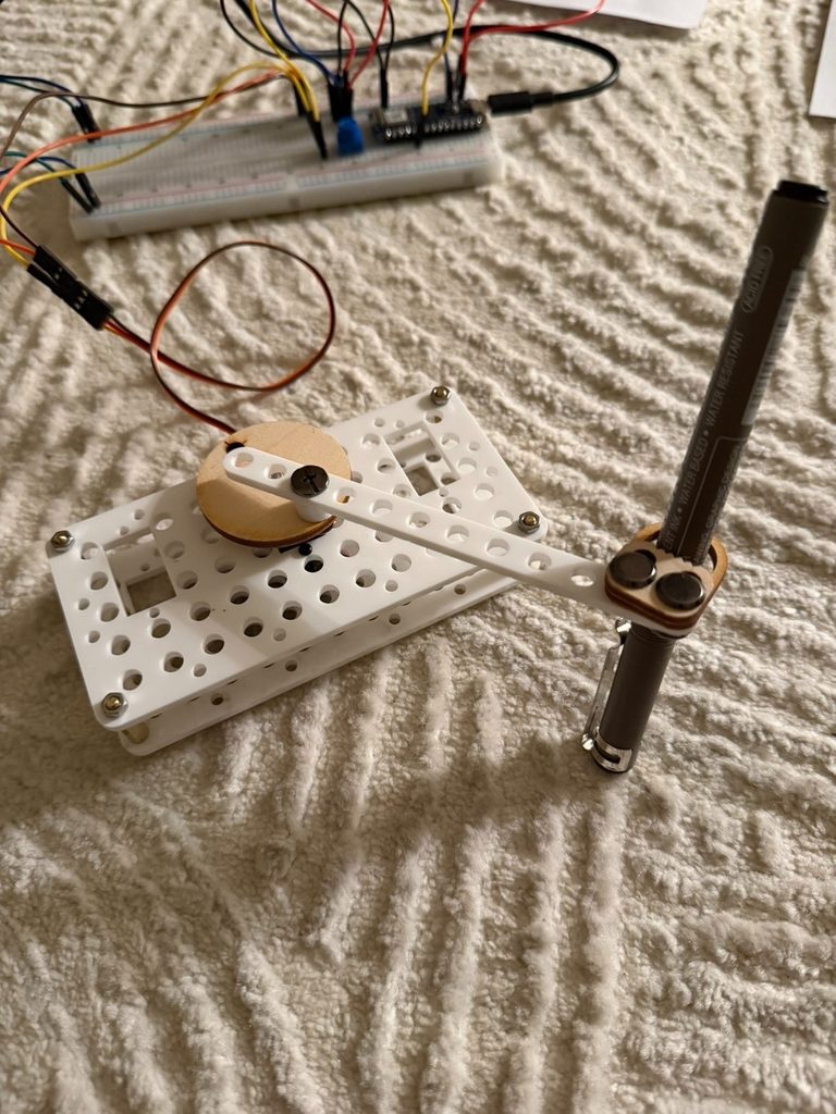
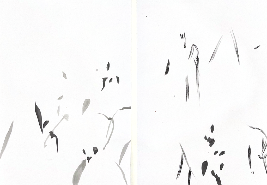
For this project, we built a simple mechanical drawing machine that uses servo‑driven motion to move a pen. We decided to keep the physical model very minimal with only one linkage arm and a single servo. This made it easier for us to focus on experimenting with the code and seeing how different angles and delays changed the drawings. Keeping the structure simple helped us spend more time testing motion instead of fixing complicated parts.
Photos and Videos:
Process
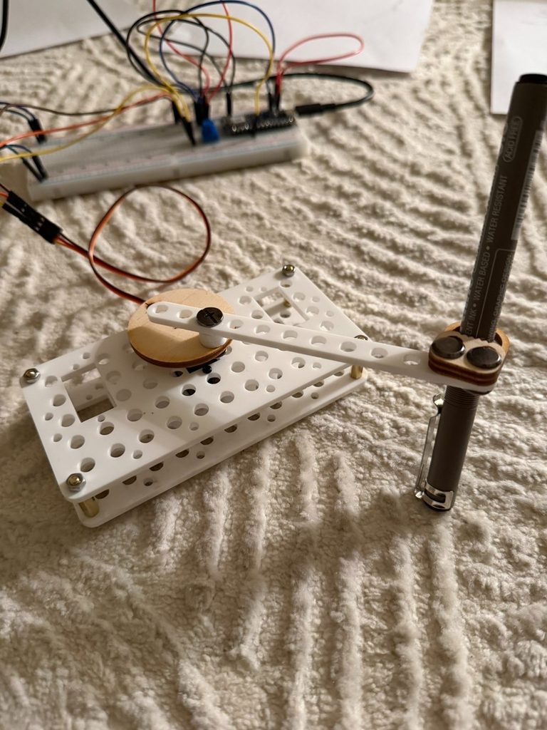
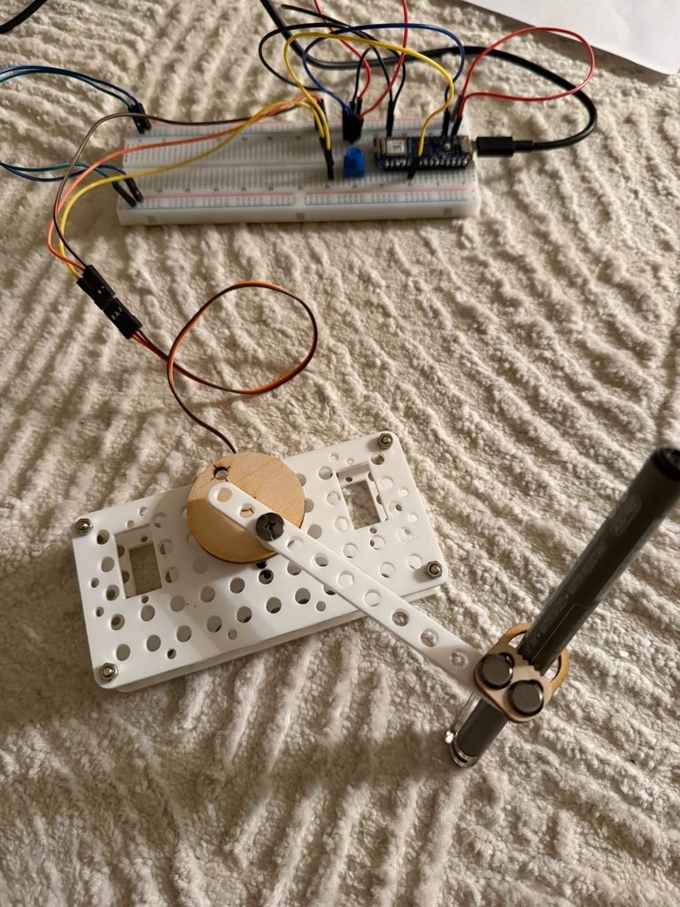
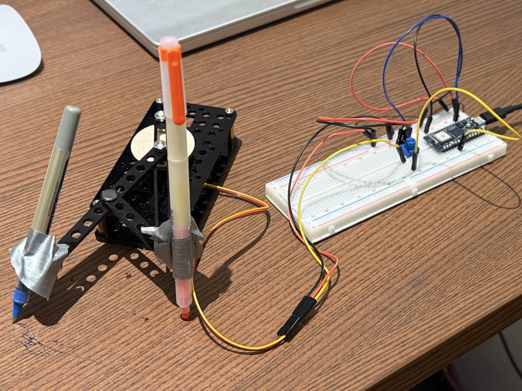
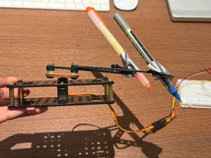
We started with the laser‑cut kit and assembled a basic linkage system. The servo was attached to a circular wooden disk, which rotated and moved a white plastic arm that held the pen. The pen was secured with small screws and a wooden bracket so it stayed steady while the servo moved.
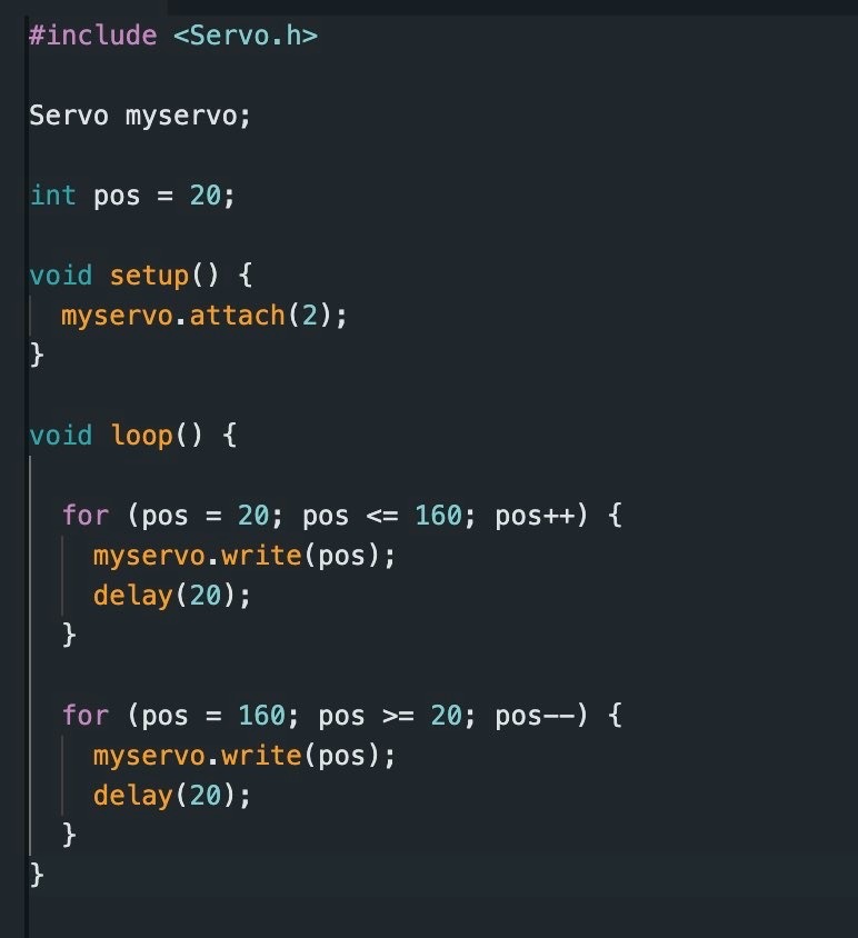
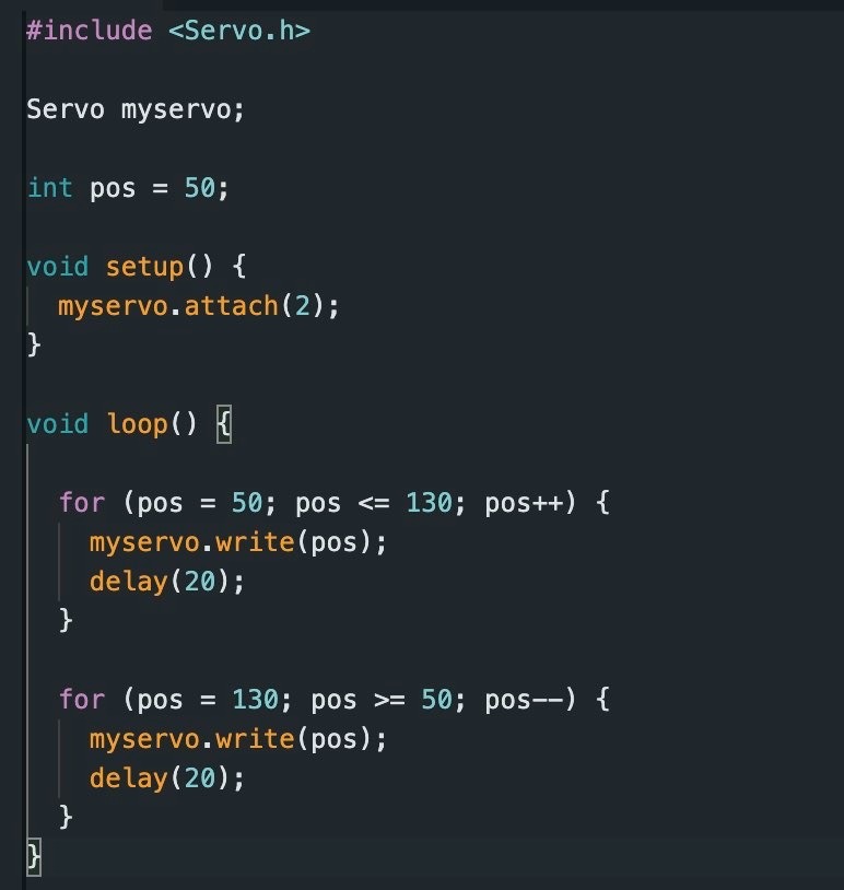
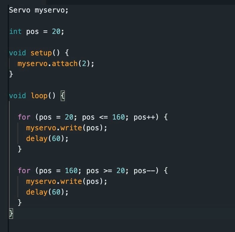
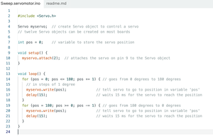
We connected the servo to an Arduino on a breadboard and wrote simple code using the Servo library. Our goal was to test different angle ranges and delay values. Each change created a different drawing pattern, so we documented them as separate trials.
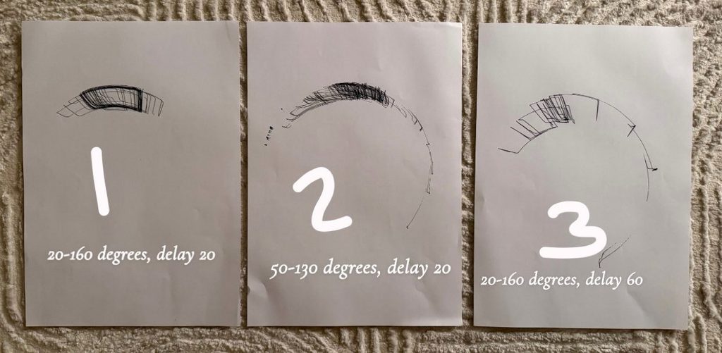
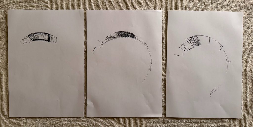
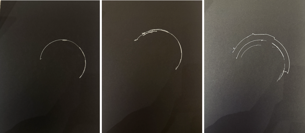
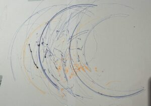
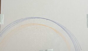
For the first trial, we used 20 to 160 degrees with a delay of 20. This created dense overlapping lines that formed a shaded arc. The fast delay made the servo move quickly, which produced compact marks.
In the second trial, we changed the angle range to 50 to 130 degrees with the same delay. This gave us a smoother and more open curve. The drawing looked lighter and more gradual.
For the third trial, we went back to 20 to 160 degrees but increased the delay to 60. Slowing the servo down created more spaced‑out lines with less overlap. The marks looked more mechanical and rhythmic.
Reflection
We noticed that even small changes in the code had a big effect on the final drawings. Adjusting the delay changed the speed of the motion, which affected how dense or light the marks were. Changing the angle range changed the shape of the curves. Faster movements created darker and layered areas, while slower movements produced cleaner arcs.
Keeping the mechanism simple helped us understand how motion becomes mark‑making. It also made it easier to test different parameters without having to adjust complicated parts every time.
Challenges
One of the main challenges was calibrating the servo so the pen stayed on the paper without pressing too hard or lifting off. We also had to find the right delay values to balance speed and control. Fast movements made the lines messy, while slower movements sometimes felt too stiff. Another challenge was keeping the structure stable while the servo moved, because the vibration sometimes shifted the setup. We also had to organize the wiring on the breadboard so it would not get in the way during testing.
Conclusion
This project helped us understand how mechanical motion and code work together to create visual patterns. By changing only a few variables, we were able to explore many different results. The simplicity of the design made the process feel more like experimentation and discovery, which is exactly what we wanted.
For this week’s project we wanted to create a drawing machine that is both random and autonomous. In other words, one that’s able to create new and unique drawings on its own every time it’s turned on.
How the Machine Operates
As far as how the machine operates, we assigned multiple variables in the code to create an interesting drawing pattern that is able to produce random results in a coherent way. For example, there is a 45% chance that one of the two servo motors will move alone for a random amount of time and within a random range, and a 10% chance that both will move.
This was coded this way, as mentioned, to create interesting results that are not too limited by the 180-degree range of the servo motors.
However, as our pals in IM lab witnessed over the weekend, our left servo would have a mind of its own and starting spinning beyond the 180 degree limit occasionally when powered on. This happened both with the old code and the new code, and we cannot understand why this happens, but it is very interesting. We could never figure out why exactly this happened but here’s a video attached.
Drawing Outputs
Process and Challenges
As for the process of building this machine, it was rather difficult at first. We found that our initial idea of building extended arms caused it to have so much weight that the pen was always going down, which made it unable to move at all.
Not only this, but during the assembly process, there were many small details that caused problems, such as the wheels on the servo obstructing the path of the arms. There were also random parts breaking out of nowhere, as well as fasteners securing the servo motors getting unscrewed unexpectedly and frequently.
Now, as for the code, we initially tried to make it so that both arms moved at a specific speed and range during each iteration, which later caused some problems. Since our goal was to make a machine that seemed autonomous and was able to produce random results, this initial code only made either V or U shapes constantly, with almost no variation in where they would go. It would essentially draw a shape and then retrace that shape immediately but just slowly.
So while we were unsatisfied with this initial behavior, we later modified the code to give the machine more freedom of movement and the almost autonomous-like movement and randomness that we were striving for.
As an experiment, we also added an ultrasonic sensor as a form of activation. The idea was that if the user removed their hand from the sensor, it would pause the drawing process; however, we sadly found the interaction to be terribly inconsistent with this and later decided that it did not really change the result that much compared to if the user were to simply turn the machine off by disconnecting it from power.
Reflection
During our process of building this drawing machine, we found that changing even the tiniest part of the drawing machine or the code generated different results, or even unexpected ones. For example, we found that having code that limits the movement while the mechanism is able to produce more results was frustrating, since we knew there was a greater degree of freedom that we could later achieve.
Also, despite only focusing on this type of movement for our machine, we recognize that there is an almost endless amount of combinations that this drawing machine could produce. There are many unexplored shapes or drawing results that we know are possible given the range of movement that the servo motors offer. Nevertheless, for this time, we focused on getting our initial idea of autonomy and randomness working.
Our concept was to create abstract geometric drawings using curved lines. We connected the pen to a long arm attached to the servo motor so that the movement of the servo naturally creates smooth curves. The potentiometer controls the position of the servo, so as we continue turning it back and forth, the pen shifts within a certain range and creates more curves on top of each other. This allows the drawing to build up over time and create different geometric patterns.
Process and Challenges
One of the main challenges was building the physical machine itself. It was difficult to make the structure stand properly while also keeping the servo and pen stable. We experimented with different ways of attaching the arm and positioning the pen. Some designs were either too unstable or did not allow the pen to move smoothly. After experimenting, we found that having one long arm connected directly to the servo was the most effective design because it was simple, stable, and produced smooth curves.
Another challenge was the pressure of the pen on the paper. If the pen was pressing too hard, the servo struggled to move. We had to adjust the pen so that it was touching the paper lightly while still being able to draw.
Video
compressed video file
Drawing Outputs
For the different outputs, we experimented with how we moved the potentiometer. Moving it across a larger range created wider curves, while using a smaller range created more concentrated curves. We also changed how quickly and how often we turned the potentiometer, which caused the lines to overlap differently. Even though the machine uses the same basic movement, each drawing developed into a slightly different pattern.
Reflection
The mechanism had a large effect on the resulting marks. Since the pen is connected to a fixed arm, its movement naturally follows a curved path instead of moving in a straight line. The length and position of the arm also determine how large the curve can be.
We also noticed that the potentiometer changes how the drawing develops. Moving it slowly creates smoother and more controlled curves, while moving it more quickly creates faster overlapping marks. Repeatedly moving between different positions builds more curves within the same area and makes the drawing more complex.
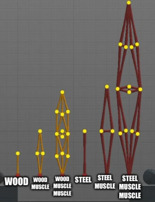
The original concept for this machine comes from a design of a “muscle” from the game poly bridge, which a game about building bridges. Here is what steel/wooden muscles look like:
This inspiration comes from how those wood/steel segments remind me of linkages. The game also has a mechanical part with hydraulics that I could have used as a reference as well because I think it’s relevant since we are using servos.
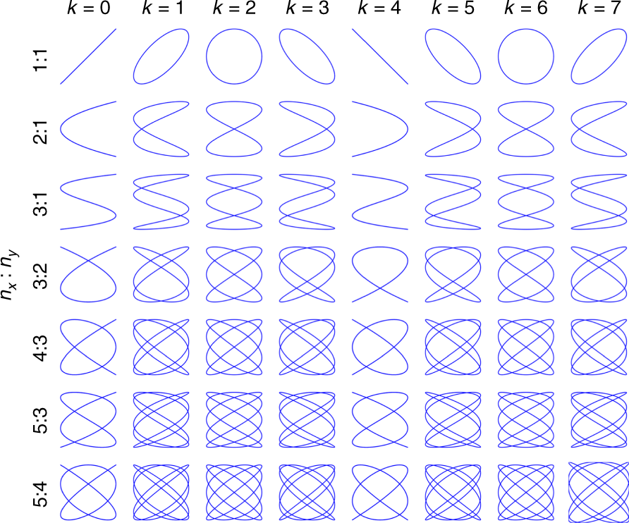
I also am inspired by Lissajous patterns, Lissajous patterns are elegant mathematical patterns formed when two oscillating motions act at right angles to each other.
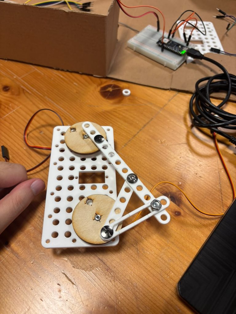
Before trying to implement something similar, I prototyped with random linkages and random anchors here and there.
This allowed me to understand how each link could influence and limit the other. I think I found this assignment particularly difficult because it was supposed to be a group assignment and due to circumstances with my teammate I had to do it alone. I ran into a couple of issues like fitting the horns on the servo and the chicago screws on the horns which I realized then I have to use a mallet to push them in slightly.
I then implemented the linkage system in my mind and moved it manually with my hands before writing code to see how things would turn out. Also before this step, I marked each starting and ending point of the servos to understand their range of motion from 0-180 to know what to expect movemenet wise before I start moving the linkages with code.
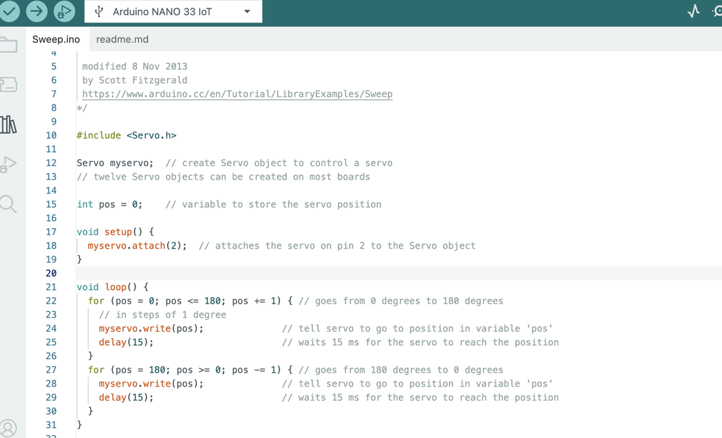
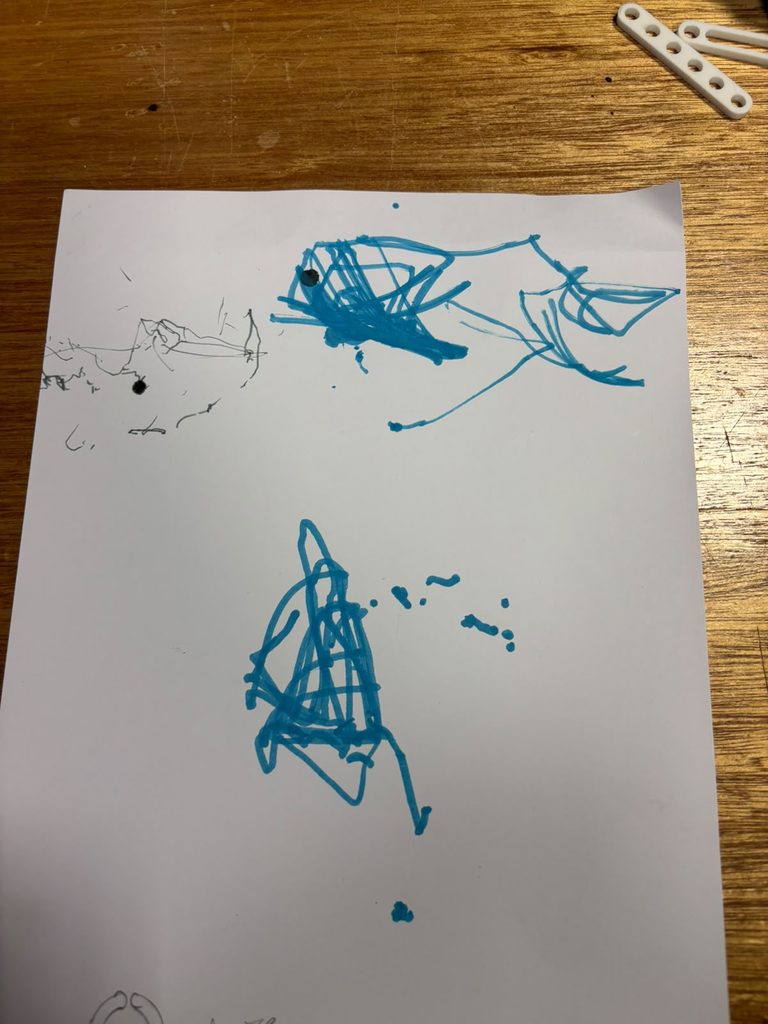
I then took inspiration from the sweep code and offset the servos a little bit but you can see that the movement s pretty limited and I couldn’t really figure out how to change the linkages in a way that keeps the original idea but also draw better results and not get stuck
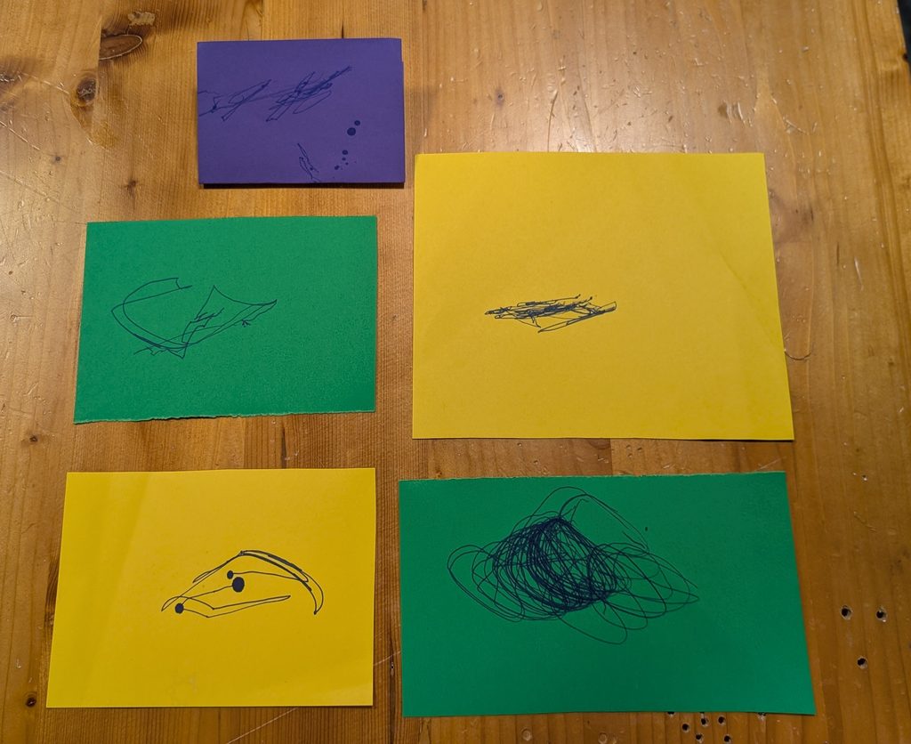
This design produced these results in blue.
I realized that the anchor would start moving after a bit and the design isn’t really looking how I want it to look, so I experimented with a different design using slotted parts as professor jack instructed during office hours and instead of using a sharpie I used a finer pen. Moreover, the system wasn’t very stable so I drilled into a wooden board and I screwed the project on it using m5 bolts and nuts.
Here’s the final design
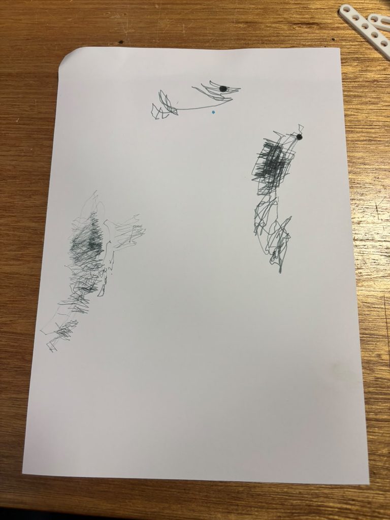
Here are some drawing outputs, each block of drawing is a different iteration.
Honestly I am not too happy with this how turned out as I couldn’t create something that slightly resembles Lissajous patterns but I definitely learned a lot. Hopefully later on if we revisit the assignment in a different form I would definitely be more prepared for it. Overall though I think this class really pushes you to learn something different and new and I believe it should be a 3000 level course.
I think changing the drawing instrument here really affected how the result looks, i think a finer pen worked really well in demonstrating the robotic movements of this system. Also, switching from normal linkages to slotted ones added a very fast shift every now and then that added a lot of life and scale to the drawing.
So the basic idea behind this assignment was to build a small scale drawing machine powered by just one servo motor, but I it rigged up to control two pens at once. I ended up going with the sweep code (the classic back-and-forth servo motion) mostly because when I first tested it out, it drew these really clean, smooth semicircles and I immediately thought I can actually turn this into something. It felt like a good jumping off point since the motion was simple but had a lot of potential once I started messing with pen placement, type of pen, and timing. I mainly used the laser cut kit provided in class to build a sturdy two layer base with two arms sticking out to hold both the pens. At first, I started with one pen, but that felt too simple and I knew I could push myself further, so that’s what gave me the idea to figure out a way to still use one motor but change the output completely, with two pens.
Sweep Code:
Drawing Outputs:
Attempt 1: Randomness
I ran through a couple of different attempts to see what kind of marks I could actually get out of this thing. My first attempt was basically just chaos, I grabbed a bunch of random pens and markers I had lying around and let the machine go, mostly just to see what would happen. It ended up looking super scribbly and layered, honestly kind of like a tangled mess of arcs (you can see all the overlapping lines and stray dots where the pens skipped or dragged). It wasn’t pretty, but it taught me a lot about how the machine actually behaves under different pen weights and pressures.
Attempt 2: (Rainbow)
For my second attempt I tried to be a little more intentional and went for a rainbow. This one came out way cleaner since I was only using two pens (orange and blue) and let the sweep motion do its thing without overloading it. If I had more time or a bigger base, I’d want to scale this up and add more pens so I could get a full rainbow with all the colors instead of just two arcs. That’s definitely something I want to try in a v2 of this build.
Process and Challenges:
Honestly, the biggest challenge I faced was the weight of the pens and markers against my base. A lot of the pens I wanted to use were just too heavy for the mechanism, and once I tried mounting two of them at once the whole thing got wobbly, unstable, and fell apart. Like it just couldn’t hold the pens steady enough to draw consistent lines. My first instinct was to screw the pens directly into the arm for a more secure hold, but that ended up making things worse because the screws added extra weight right where I didn’t want it. So I ditched that idea and just used duct tape instead, which sounds kind of messy but actually worked way better since it was so much lighter and let the arm move more freely.
Reflection:
Looking back, this assignment really showed me how much small changes in either the mechanism or the code can completely change the output. Something as minor as switching from screws to tape, or slightly adjusting the type of pen I used, made a noticeable difference in whether the lines came out clean and arc-like or messy and scribbly. It’s kind of a cool reminder that with these physical computing projects, the code is only half the story, the actual hardware and how it’s built matters just as much for the final result. If I kept iterating on this, I think focusing on the balance and weight distribution even more would let me get way more precise and intentional drawings out of it.
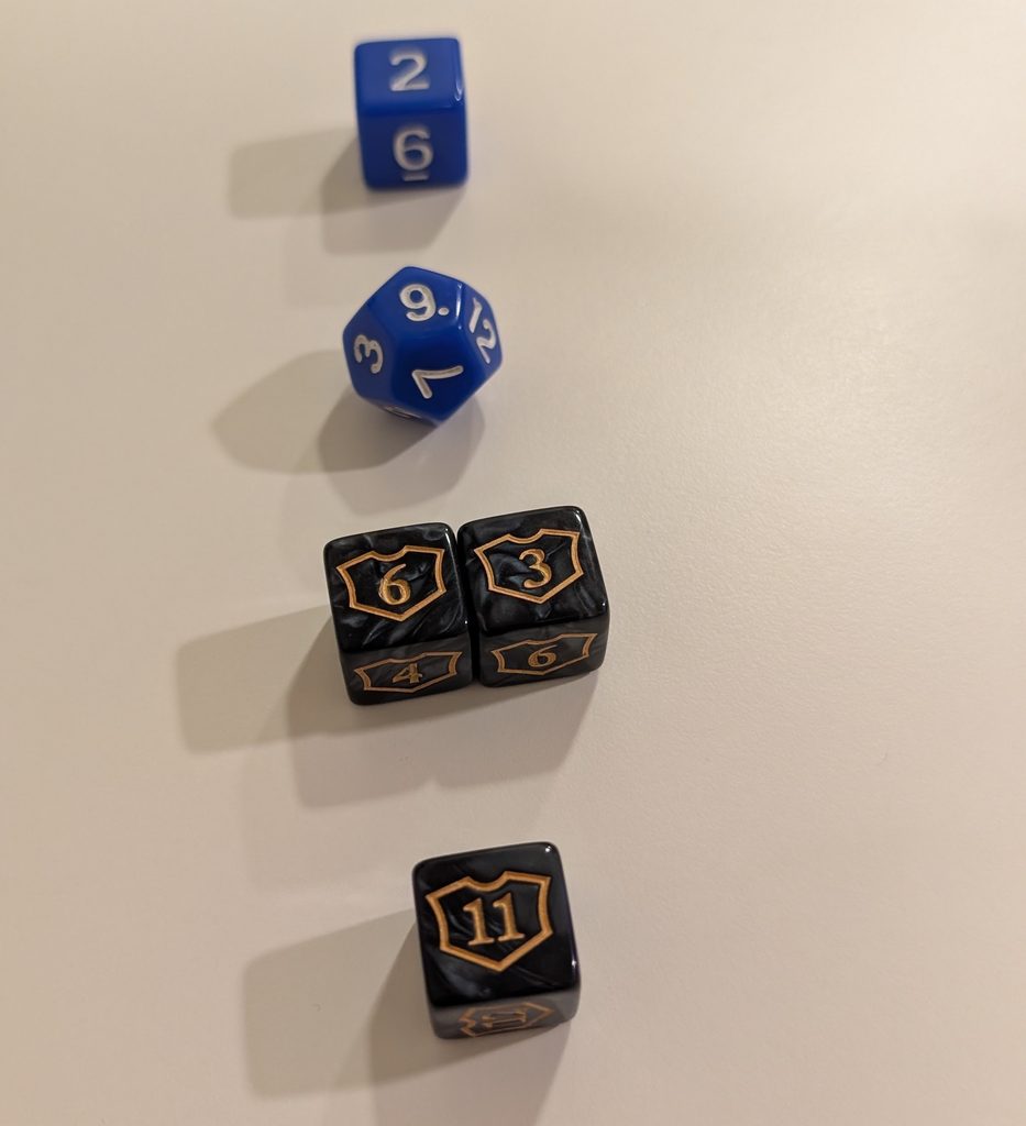
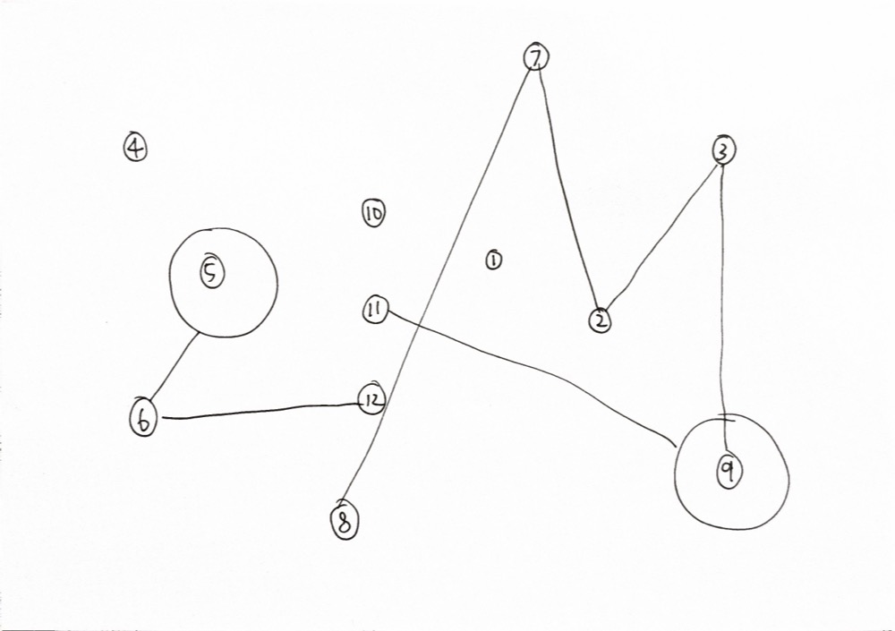
To recreate my method, the user needs a few D6 dice and at least one D12 dice. One of the D6 should preferably be numbered 7 to 12 instead of the usual 1 to 6 but you could just remember which one is supposed to be different.
Step 1: Set Up Paper
On a piece of paper, I would ask someone else to draw points as tiny circles labelled 1 through 12.
Step 2: Rolling the Dice
I will determine four individual values indicated as points A, B, C, and D. This is how the values of ABCD are determined:
Point A = Result of Blue D6
Point B = Result of Blue D12
Point C = Sum of Two Black Marble D6
Point D = Result of unique D6 (7-12)
Step 3: Connect the Points
Let’s say for example point A is 3 and point B is 12, I’m going to draw a straight line from the point labelled “3” to the point labelled “12”. If point C is also “12” then that’s where I came up with a new rule:
If any two numbers overlap back to back, I would draw a circle around that point.
Step 4: Repeat
Repeat Step 2 and Step 3 again two more times. That should create a pretty interesting visual.
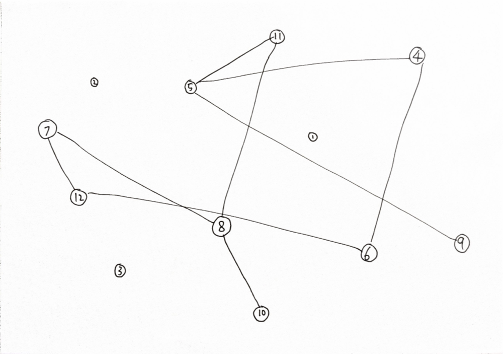
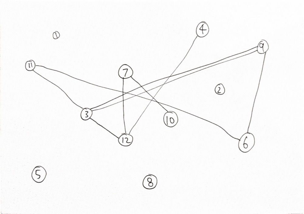
Result:
Process & Challenges
Originally I was pretty perplexed on how to approach this project. I think the example video with the oscillating fan led me seeking out something mechanical throughout the week. I had considered my skateboard trucks, the A5C dorm elevator door, and even some gym equipment (which they definitely would not have allowed haha).
So I got my current idea when I met up with a friend to play a card game, Magic the Gathering, and remembered I had some pretty interesting dice at my disposal. Specifically I had dice that were D6 but started from 7 and ended at 12. They’re usually used to track planeswalker loyalty (a variable stat that’s basically their health points), but they could definitely make for something interesting here.
Reflection on Control, Chance, and Authorship
When I first designed this system, I actually was expecting a lot more repeating numbers so I could create interesting patterns with stacking circle shapes, but in practice it only showed up twice and only in the third attempt.
The dice introduced chance into the whole equation but perhaps if I wanted a specific aspect of the result to appear more often(such as the circles), then I needed to adjust the number of potential outcomes and the probability of each outcome to create something more visually riveting. For example, Maybe I should have just used 6 points instead of 12 points.
In Response to Sol LeWitt
I believe LeWitt would agree that the idea of my drawing lies in the rules of my system that I designed– the repeatable process that anyone can perform. It’s obvious that no two people and not even two different results will appear the same.
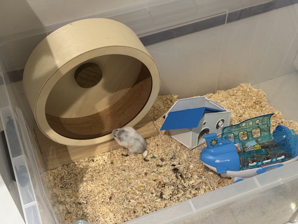
My younger brother Abdulla has two pet hamsters. He takes great care of them, giving them a large tub to stay in and every so often he takes one of them out to see the rest of the world. During the day we hardly ever see the hamsters, they are often hidden underneath the ground. This begs the question: what could they be doing underground? Could they be artists secretly perfecting their craft underground?
Abdulla insists that hamsters are nocturnal by nature; they sleep at night and only come out at night where you’ll often see them running on their hamster wheel if you’re awake at the time to see it in the first place and during the day they’re asleep. I however, have rarely seen them on their hamster wheel in the evening, usually because I’m asleep by that time, and do occasionally see them above ground in the day. I ignored my bias and instead I’ve been comparing them to the famous artist Leonardo Da Vinci.
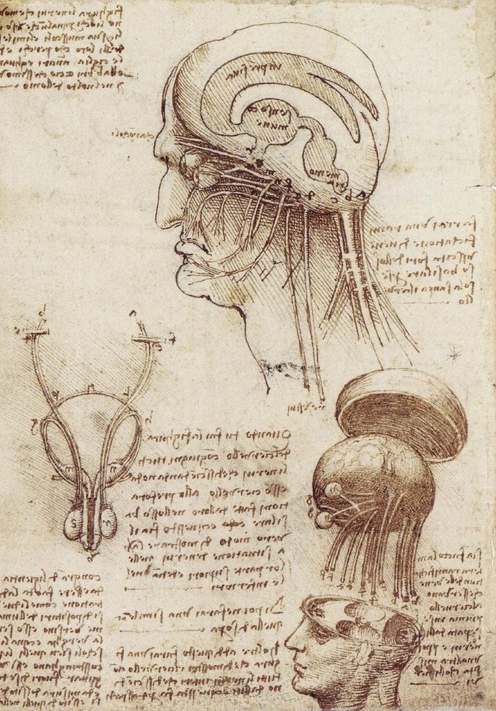
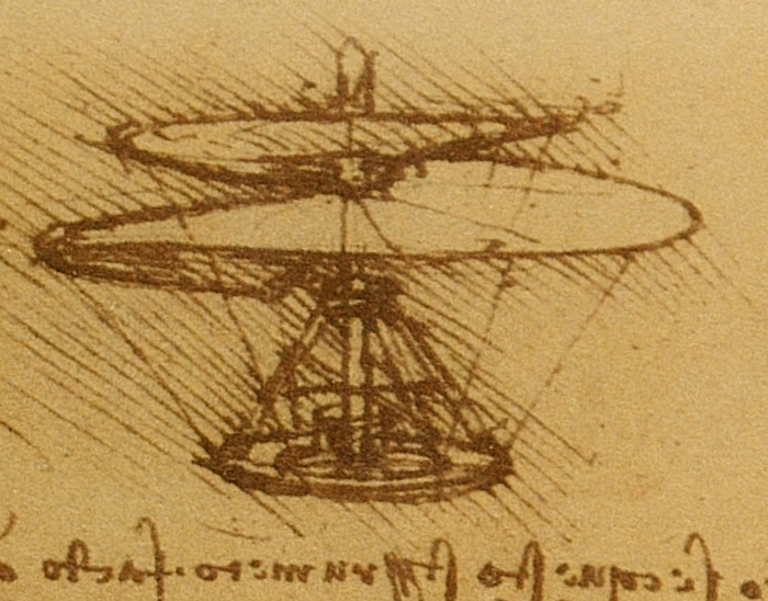
Da Vinci is often known for being an artist but not enough people realize that behind his art was an incredible effort to study the physical world: For example anatomy.
He accumulated 13,000 pages of notes throughout his life consisting of his observations developing a scientific understanding of the physical world but rather than using semantics he would often draw what he saw [1]. He would also draw his own ideas or thoughts of new creations or inventions [1].
Yet only few knew or saw his personal notes during his lifetime except his pupils.
The hamsters may be exactly the same. Creating mental notes and studying the world during the day based on the observations around them but especially when Abdulla takes them out. Now all that is left is to see what they are capable of producing. I couldn’t yet tell Abdulla directly that they could be the next Da Vinci so instead I enlisted my other brother Ahmad to create a plan.
Concept
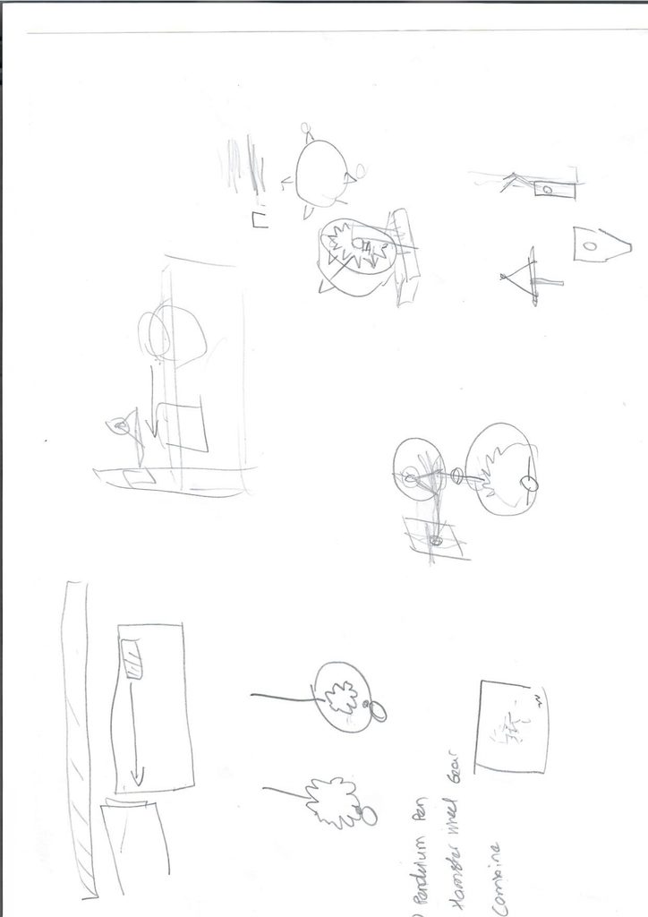
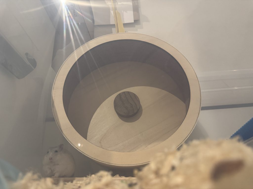
Ahmad and I arrived at the plan to direct the rotation of the hamster wheel to a pendulum with a pen attached or for short Pen Pendulum. On the back of the hamster wheel would be a gear made of cardboard. The teeth from the gears would strike an extension plate attached to the pen which would strike a piece of paper creating a drawing of some kind. The paper would be attached to a dresser near the tub.
We would create the Pen Pendulum first, then create the gear, then combine them together. Moreover, we only planned to have this setup for about 10-20 minutes just long enough to get the hamster drawing something rather than leaving it overnight. As otherwise we were worried that the marker may fall into the pen and harm the hamster in some way.
I originally proposed using a normal pen or pencil but Ahmad was right in saying a whiteboard marker would be better because the strikes will rarely hit the paper perfectly and the large tip of a marker would be far more consistent.
Ahmad and I later explained our plan to Abdulla. He was surprisingly excited and was happy to help.
Implementation
Step 1: Cleaning the wheel
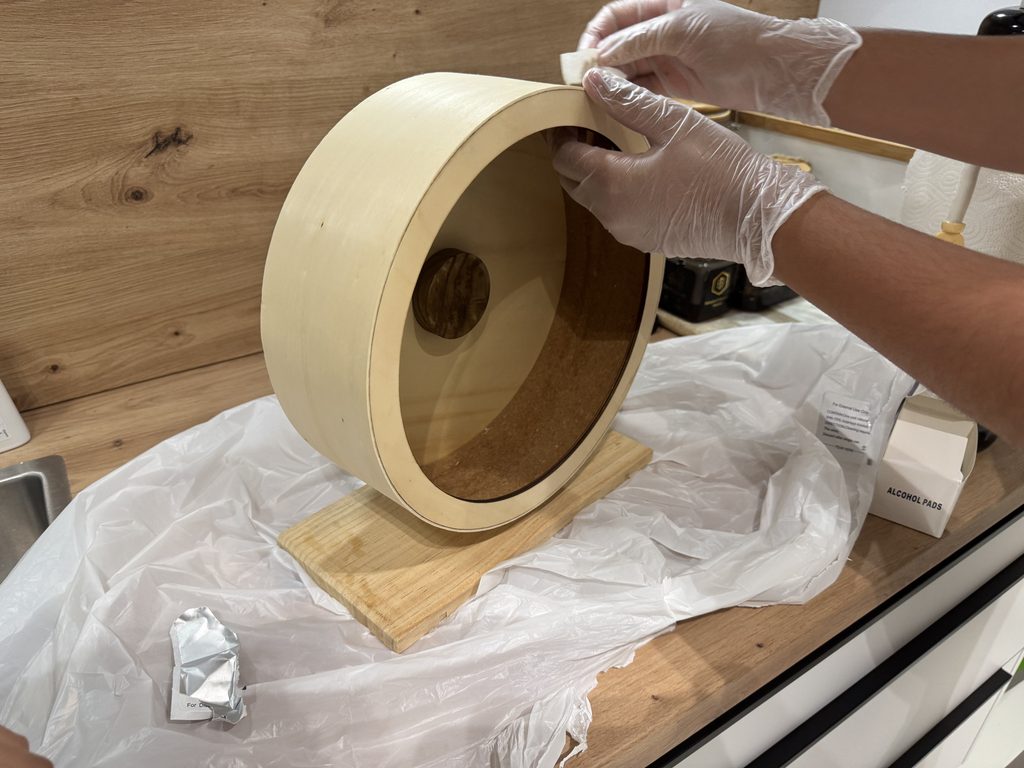
Our first step was to clean the hamster wheel for when we would later attach the gear. Abdulla explained to us that we shouldn’t use water for the wheel since it was made of wood. Instead we used alcohol wipes in moderation and let the alcohol evaporate while we went to work on the Pen Pendulum.
Step 2: Pen Pendulum
We first found an area wherein we could develop our setup before ever putting it in the tub with the hamster.
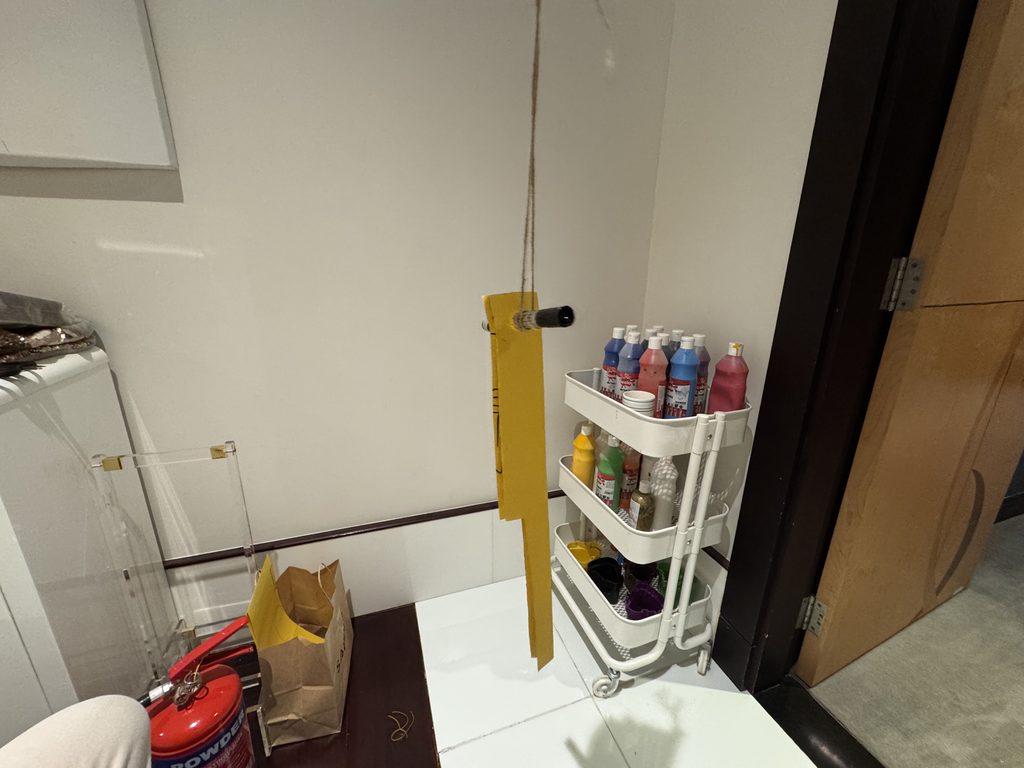
The Pendulum was by no means precise. We used double sided tape to make sure the thread stays in place. The extension plate was made of paper. Ahmad also realized as he was making the extension plate that to accommodate for the wall trim we needed to make a cutout.
Step 3: Hamster Gear
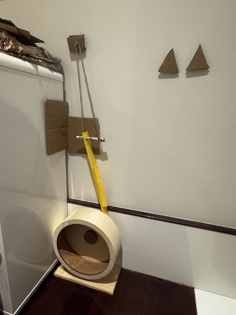
Gears attached to the hamster wheel using double sided tape
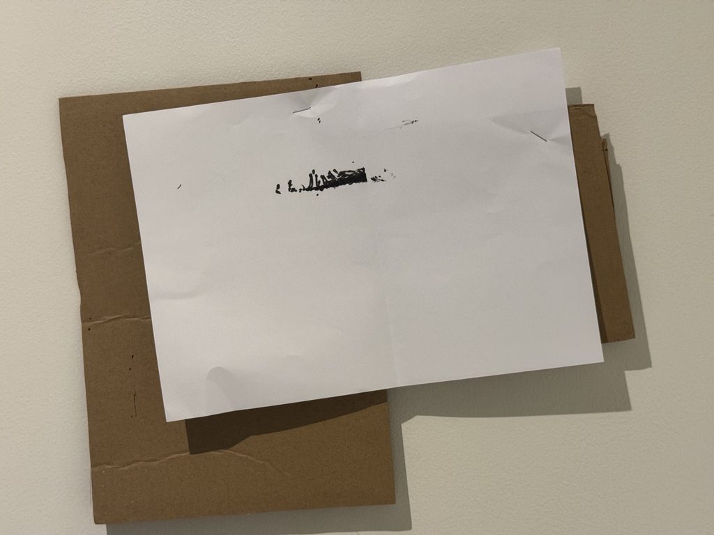
Rather than make a big gear and tape it on the back of the wheel since all we had were A4 sized sheets we used small triangles as shown. And did some quick testing wherein we realized that we had to make three changes. First, the canvas which in the picture was just cardboard needed to be offset from the dresser. Second, the paper would need to be folded in the middle since occasionally the pen would strike the side rather than just the front. Lastly, we originally planned to stick in 4 gears but reduced it to two since otherwise the hamster wheel wouldn’t give enough time for the Pen Pendulum to oscillate back.
Step 4: Putting everything together
The first thing we did was put the hamster wheel in. It used to be on the right hand side of the tub but we moved it to the left side. We also gave some time for the hamster to get used to the wheel again; because we’d cleaned it, it no longer had the same familiar scent as it did before and we were sure that there was no smell of alcohol left in the wheel before ever putting it back.
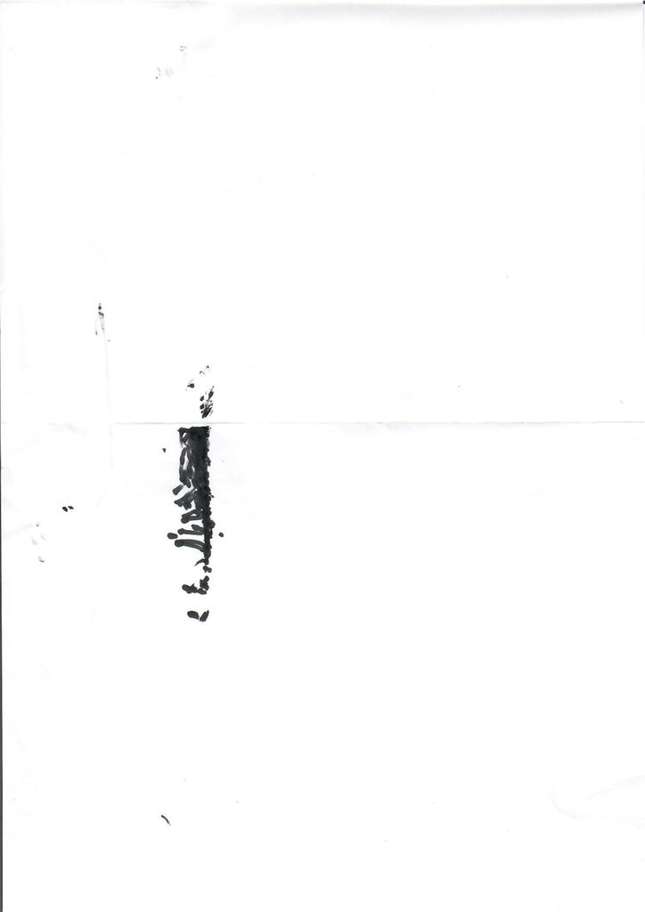
During our initial tests without the paper we were testing to see if the hamster was comfortable running on the wheel or not. During these tests we were making some adjustments to the pen and extension plate. The end result was a drawing that almost looked like a face. However, we couldn’t claim that this was the hamster’s work alone because there was human intervention.
Result
We stapled a piece of A4 paper to the cardboard while making sure to not damage the wall and waited to see what the hamster would produce.
All the hours of meticulous studying underground from observations of the world around him but without the tools necessary produce all of what he had learned. But finally, we had finally created a tool for her to express herself through art.
Improvements
There are many things that could be done in the future to improve our design.
Creating a more stable Pen Pendulum
The pendulum meant that the drawing could only be 1 dimensional, maybe a different design could create a 2D Image.
All things considered while our design was certainly low-tech, we’re glad that it didn’t disrupt the hamster’s lives. And since we removed the setup after about 15 minutes we didn’t have to worry about anything falling into the pen and fortunately nothing did.
Acknowledgements
Before this assignment I had hurt my ankle quite badly and wasn’t sure how I was going to complete my plan let alone start it. I can’t thank my brothers enough for helping me not only with this project but as I’ve been recovering.
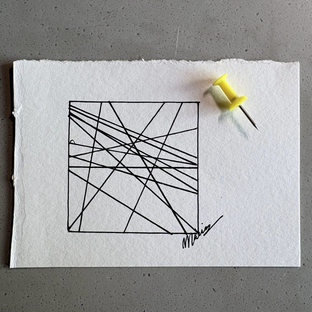
For this Assignment, I took inspiration from Jonas Spieker’s 100 Spins, where he spins a coin marked with two lines exactly 100 times and draws a line across the paper wherever the coin lands. The result is almost entirely chance, held together by a very small set of design rules.
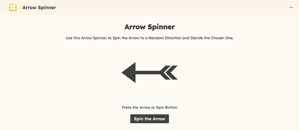
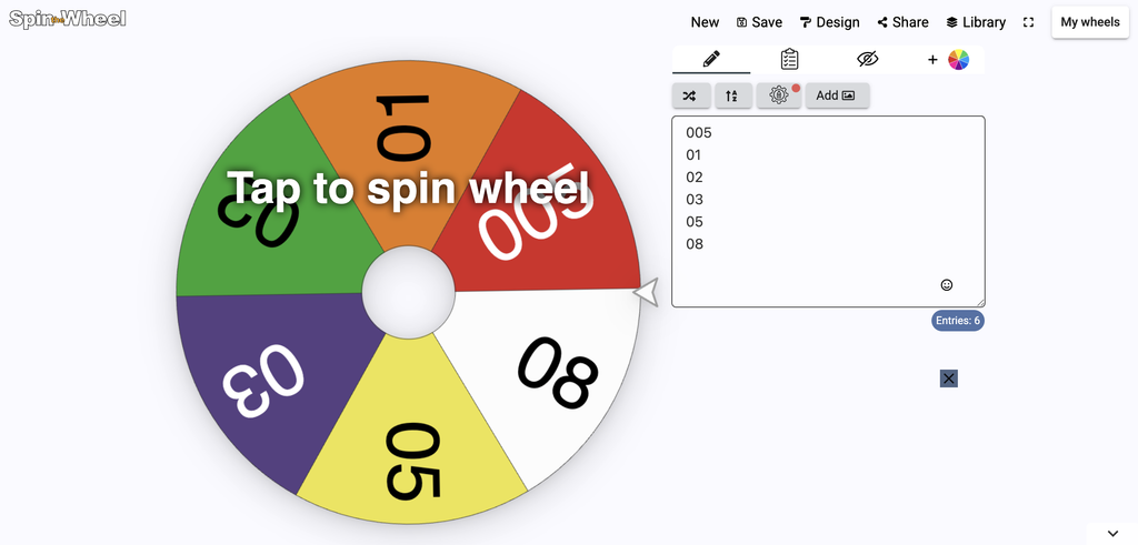
I wanted to try a similar idea but with more than one variable in play. Instead of one randomizer I used two spinners on my iPad. The first picks a pen thickness from my set of Microns (005, 01, 02, 03, 05, 08). The second picks the direction of the next line. Even though the spinners are digital, but they do the same job a coin or a dice would do.
The system
Outputs
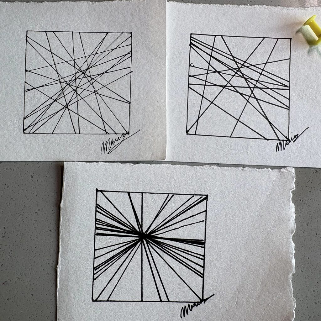
I made three drawings, each with one rule changed.
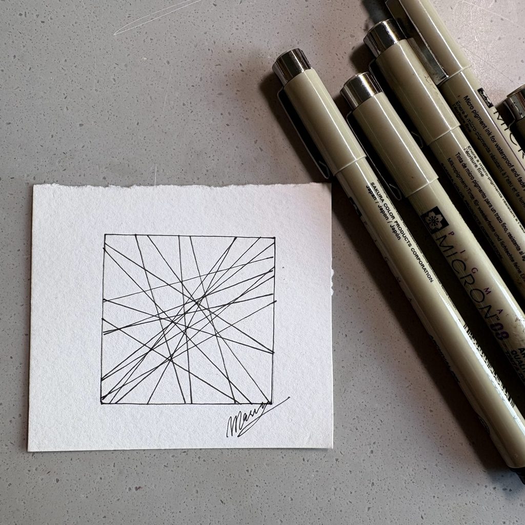
The first one is the base system. I spun for direction and drew the line, over and over, until it felt finished. Micron 02.
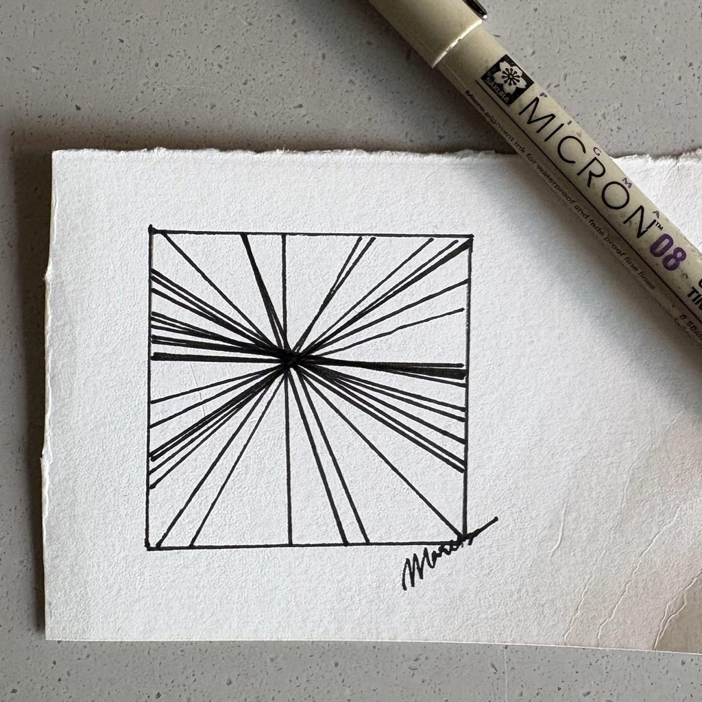
The second one keeps the direction spins with the arrow but forces every line to pass through a single point. Micron 08.
The third one uses a thumbtack instead of a spinner. I dropped it on the page and started each line from wherever it landed, running in whatever direction it pointed. Micron 05.
Process & Challenges
I spun for thickness before each drawing. However, what I did keep control of was when to stop. Spieker decided on 100 before he started, so the stopping point was already out of his hands. I just drew until it looked done to me. So the directions are chance but the density is mine, and I think that is one of the biggest differences between his drawings and mine.
The second drawing is the one that surprised me. It feels like the same amount of randomness as the first, but pulling every line through one point made it look planned and intentional. I did not expect one small rule to hide the chance that completely.
I also signed all three without thinking about it (out of habit). It only made me question later: how much of a drawing is truly mine if I leave it up to a protocol and chance?
Control, chance and authorship
In relation to LeWitt’s Paragraphs on Conceptual Art, the idea sits mostly in my design decisions, not in the machine.
LeWitt says that the idea becomes a machine that makes the art, and his wall drawings were installed by draftsmen he never met. That works because the instructions were complete. Nothing was left for the person holding the pen to decide.
Mine are not complete. My rule set had gaps in it: the stopping condition, the pen weight, whether to constrain the lines to a point. I filled every one of them myself, in the moment, while drawing. I could not hand this protocol to someone else and get my drawings back. That makes me the author much more than the system is.
If I ran it again I would fix N before starting and try to give the whole thing to someone else to execute. Then the answer might genuinely be the machine.
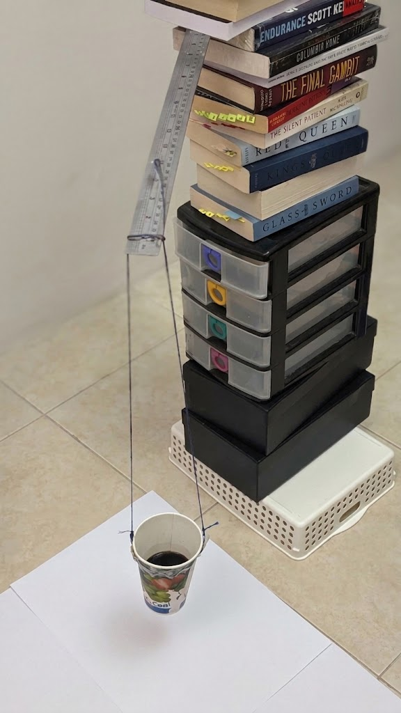
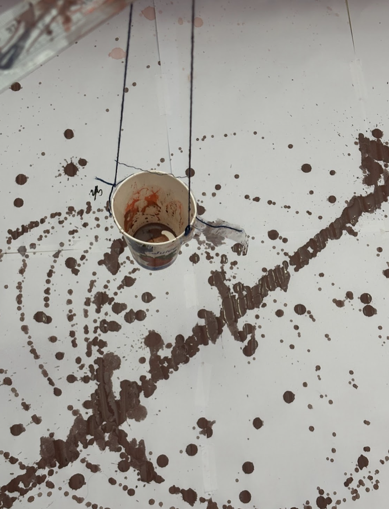
For this assignment, I built a Low-tech pendulum drawing machine using a paper cup filled with watered-down paint attached to two strings. The paper cup has a small hole punched into it, allowing paint to drip from it onto the paper underneath as it swings. The idea is that the unpredictability comes from how the material flows across the canvas (in this case, paper), with the use of the swing’s angle, speed, and the type of material and how they each affect the marks left, but not in a way I can fully predict or control in the moment.
Video
Process and Challenges
I built the base of my machine by stacking boxes and books into a tower, with a metal ruler laid across the top to suspend two strings. My first attempts used embroidery thread attached to a paint marker, then a paintbrush as drawing tools. However, I found that all three methods caused the friction between the tip and paper kept interrupting the swing, which made short streaks. I thought the reason could be the height of the pendulum but even when I lowered the string so the tip barely grazed the paper, the friction still caught and stalled the motion.
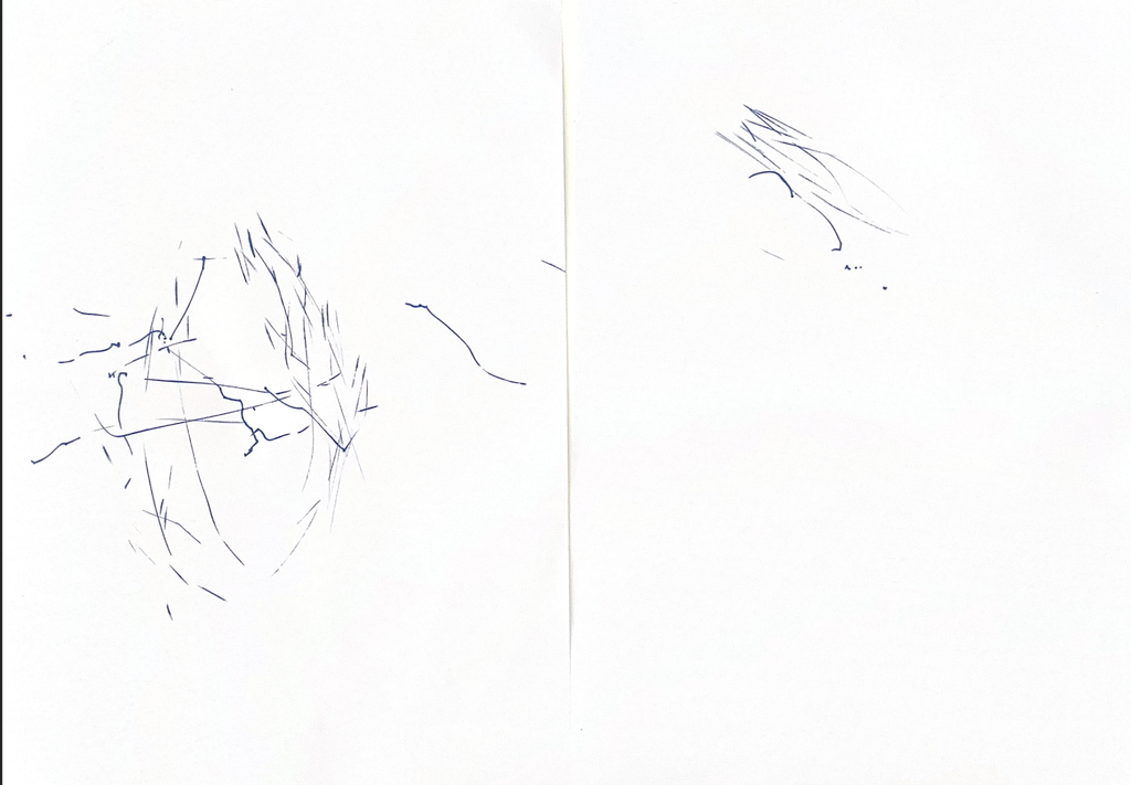
Trial 1 (With a Paint Marker), the swing looped over the same spot, which resulted in streaks.Trial 2 (With a Paintbrush dipped in ink), short strokes and scattered dots from the brush’s movement.
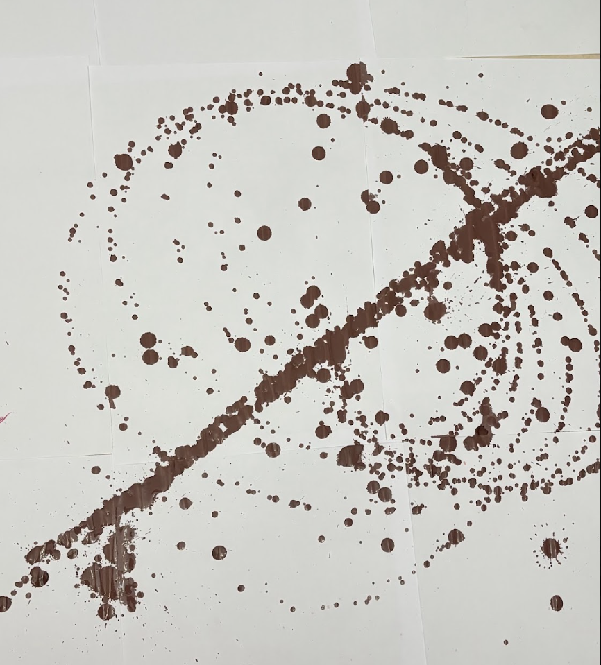
As a result, I decided to experiment further and switched to a paper cup filled with watered-down acrylic paint, with a hole poked in the bottom. This let the paint drip out as the cup swung, and let me control the flow through the angle and speed of the swing. Surprisingly, the biggest challenge was the paint’s consistency (thickness), since if it was too thick, it dropped in blobs instead of flowing into lines, and if it was too thin, the color became barely visible against the white paper.
After mixing colors, it thickens the consistency, so I added more water to bring it back to a flowing consistency. In addition to this, taping and releasing the cup was also tricky, since paint started leaking the moment the tape came off, so I had to move quickly once I started.
Final Result with paint
Reflection
In relation to Sol LeWitt’s Paragraphs on Conceptual Art, the “idea” of my drawing resides in the machine and my design choices since the pendulum system itself was set from the start, though it took some exploring to find what tool to pair it with, but once running, the machine determined the specific marks I couldn’t control.
Sol LeWitt in his Paragraphs on Conceptual Art argues that once an artist sets the basic rules of a plan, the fewer decisions made afterward, and removing the arbitrary and the subjective from the process (13). In my case, I only arrived at using a cup of paint after testing a paint marker and a paintbrush. Even once I landed on this tool, I kept changing paint consistency, switching colors, re-thinning the mixture.
In addition to this, he says the basic form used should be simple and uninteresting, so the focus stays on the arrangement it creates, not the object itself (LeWitt 13). In my case, the pendulum’s swing isn’t interesting on its own, but the marks it produced are. He also argues that the in-between steps of making art, like testing, adjusting, and failed attempts, matter just as much as the final piece, since they show the artist’s thought process, which is sometimes more interesting than the final product (LeWitt 14). Looking at my own process this way, it taught me that I figure things out by physically testing them to see what the results are like.
My concept comes from the motion of doing simple things daily. I tried to get inspiration from mechanical things we utilize everyday and after a session of brainstorming I got up from my chair and opened my door. But there it was, that motion of holding the door handle and pushing it down inspired me to trace the arch that forms from moving this handle. So I attached a pen to the handle and tried to trace that motion
I unfortunately do not have paper and couldn’t get access to it as there aren’t bookstores near the area I live in (I live off campus) even though I could swear I had a note book somewhere. I will figure this out on Monday as I buy a notebook from the bookstore for this purpose.
Revision after getting paper:
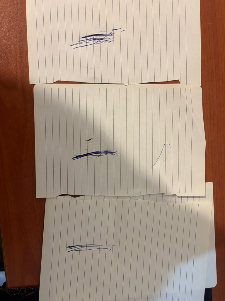
These drawings are ordered from top to bottom as first to last. The first iteration was pretty chaotic and it scratched my door so that’s 500 AED i gotta pay for the landlord at some point, the second iterationi got the hang of the motion more and put the right amount of pressure on the pen and the motion was seamless.
To be honest this is not what I expected AT ALL. I expected a smooth curve that looks like an arc thats situated on the same spot, but I instead got a lot of jagged and staggered lines, which is interesting. What is interesting to me also is that the drawing could really scale up or down depending on where you put the pen on the handle, say you put it directly on the center of the knob, it wouldnt move at all, while on the other side a clear arc will form.
Some of the challenges that I faced is genuinely the simplicity of the assignment. I found it really hard to think of something low tech and because of the video we saw during lecture of a pen attached to a fan, my brain was fixated on using a machine that has a perpetual motion that I can replicate like the fan video. I am happy that I instead came up with an original idea of using the door handle and didn’t tunnle vision on the video we saw.
my other idea was dipping a marble in a jar of ink and spinning it in a bowl with a paper inside and trace this motion, but I found the concept of the door handle more appealing to me.
Thinking about control, chance, and authorship in this assignment, I’d say I’m mostly in control but I did leave room for a little bit of chance. I decided the handle, the pen placement, and the general shape of the motion, so the core idea is fully mine, but the exact line that gets traced depends on small things I can’t fully predict, like how steady my hand is when I press the pen against the handle or how the pen reacts to the material of the paper on the door. So even though I set up the whole system, the actual mark has a bit of its own personality that comes out once I let it run. In terms of authorship, I still think of myself as the artist here even though the handle is technically doing the “drawing.” I’m the one who noticed the motion, chose it over other ideas, and built the mechanism to capture it, so the authorship comes from that decision-making process rather than from physically holding the pen and drawing the line myself. It’s kind of similar to what LeWitt says about the artist selecting “the basic form and rules that would govern the solution of the problem,” where after that point, the fewer decisions I make, the more the piece is really about the idea instead of my hand.
The idea of my drawing definitely comes from the design decisions I made and not the machine or the final drawing itself. The handle and pen setup is really just a tool, it just repeats whatever motion I already picked out for it. The final drawing hasn’t even happened yet since I don’t have paper, but I already know exactly what the concept is and how it will look, which kind of proves that the idea existed before any physical form was made. LeWitt talks about how “the idea becomes a machine that makes the art,” and I think that fits here because once I made the decision to use the handle, the rest is just letting it play out.